Ballistic Pendulum Lab
Name: Kyle Collins
Lab Partner: Hunter McCabe and Mary Schaude
Date: 18 February 2015
Purpose: This lab's purpose is to demonstrate how collisions conserve momentum and to determine a relationship between momentum and energy.
Theory: The ballistic pendulum is a device designed to catch a projectile in a ballistic medium so as to determine the projectile's velocity. This is done by using derived equations such as the one below to calculate the height the pendulum rises to.
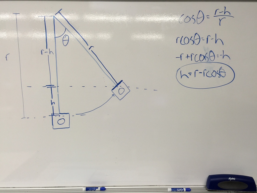
Derivation for height, which will be used later
Here, r represents the distance from the pivot point to the center of balance, h represents the height the system rose to, and theta is the angle of the system; note that the center of mass is found with the total mass of pendulum and projectile combined. In addition, there was ballast attached to the pendulum to increase mass and eliminate error by making the pendulum less likely to move around during the swing.
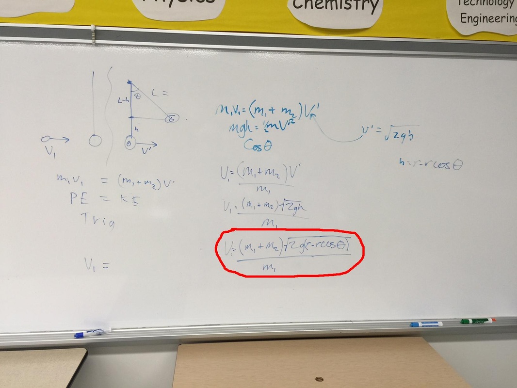
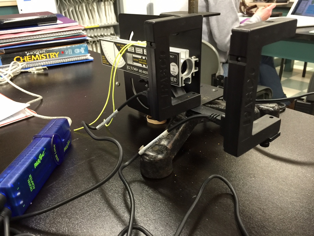
Experimental Technique: The mass of the ball (projectile), the pendulum, and both combined were recorded. Next, the center of mass for the combined ball and pendulum was found by balancing the system on the edge of the table. The system was attached to a pivoting device that would also record angles. A ball was launched out of the launcher into the pendulum, and height was found with the angle measured. This was then used to find the velocity, using the equation below circled in red.
Experimental Technique: The mass of the ball (projectile), the pendulum, and both combined were recorded. Next, the center of mass for the combined ball and pendulum was found by balancing the system on the edge of the table. The system was attached to a pivoting device that would also record angles. A ball was launched out of the launcher into the pendulum, and height was found with the angle measured. This was then used to find the velocity, using the equation below circled in red.
Entire system
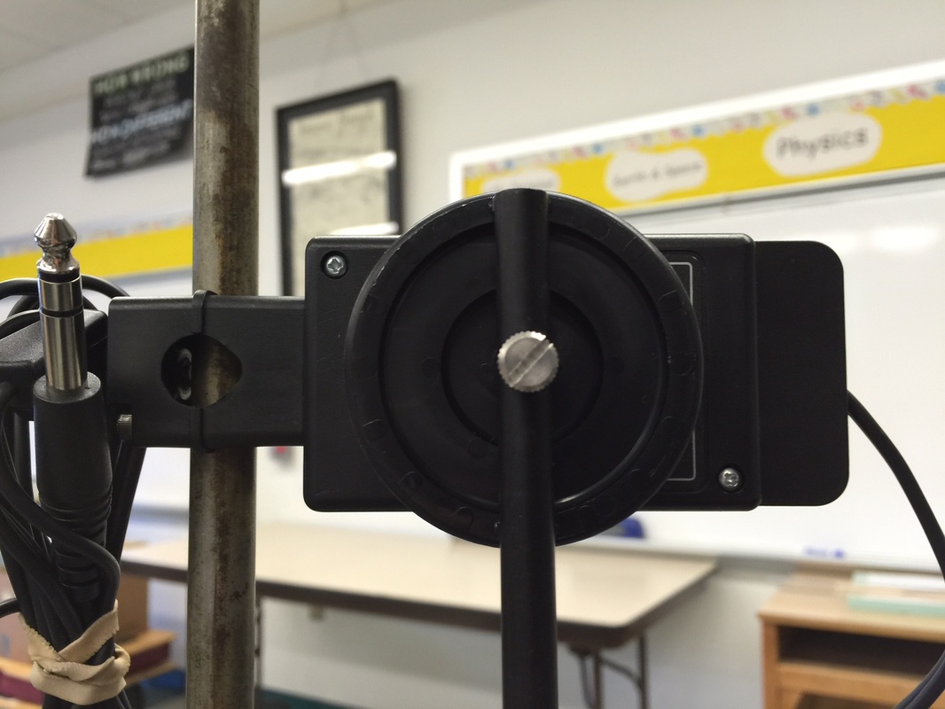
Rotational component
|
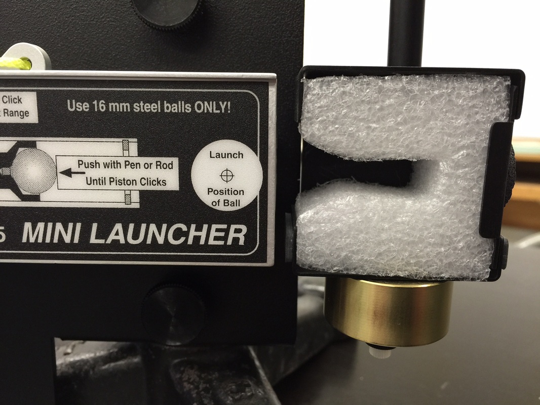
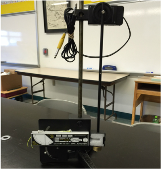
Pendulum with ballistic medium
Launcher with photogates
|
Finally, photogates were assembled and used to measure an average velocity. This was then used in a percent difference equation.
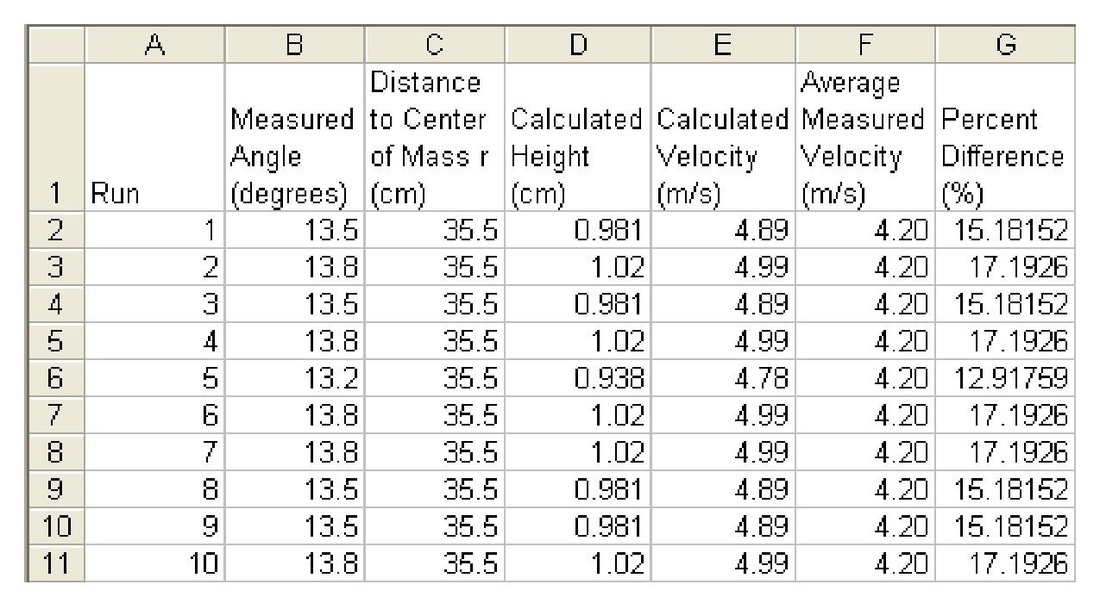
Data and Analysis: The mass of the ball was found to be 17.1g, the mass of the pendulum was 148.4g, and the total mass was 165.5g. The distance of the pivot point of the system to the center of mass for the total system was measured to be 35.5cm.
Data and Analysis: The mass of the ball was found to be 17.1g, the mass of the pendulum was 148.4g, and the total mass was 165.5g. The distance of the pivot point of the system to the center of mass for the total system was measured to be 35.5cm.

Raw data
Next, the pendulum was attached to the rotary motion sensor and the ball was launched into it ten times, yielding the data recorded in column C of the following table.
More raw data
Using these data, the height the system reached after collision was calculated using the next equation.
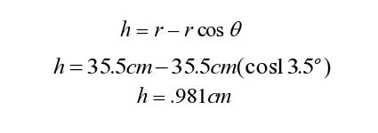
Sample height calculation
Next, using this result, the calculated velocity was achieved.
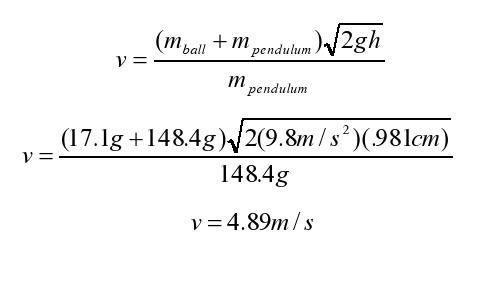
Sample velocity calculation
Lastly, the measured and calculated results were compared with a percent difference equation.
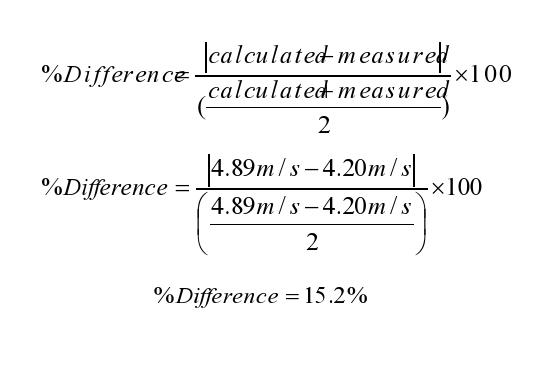
Sample percent difference calculation
Conclusion: The percent error appears too high for what would've been expected for a lab of this sort. To start, the distance measured to the center of balance could have been affected by a number of things, like the position of the ball within the pendulum and the surface it was being balanced on. The laptops used in class had a much sharper edge that the table, but still could have provided a better point for determining center of mass. In addition, the tables bowed in the middle, meaning that if the device was off center on the table, the pendulum would swing further from or closer to the launcher.
